The AVR BASIC Computer
I show you how to build a retro 8-bit computer that boots to a BASIC interpreter.

Born too early or too late... What ever your belief may be - I explore an era of computing that became lost in time despite invoking a universal feeling of nostalgia among us all. Join me as I take a trip back to 1980 with this weekend build: The AVR BASIC Computer.

From a young age I have vivid memories of computing, I was immersed in the artefacts of a booming technological age that had already come and gone by the time I arrived. Nevertheless, I was fascinated by a collection of colored floppy disks in my garage that were collecting dust, in awe of the internet and how I could type any question I may have had into Google and have it provide the information I was searching for. Not only this, the internet at the time was alive - sites were digital oases waiting for a lonesome wanderer to stumble upon them, offering refuge and social interaction that was real and meaningful.
I consider myself lucky to have experienced the tail end of this unique time in history - the joy of flipping a switch to illuminate a CRT monitor, hearing the static crackle as it warms up to display Windows 98 or XP. No matter how brief these moments were they were meaningful. But it always left me wanting more... Fast forward to today, I finally satisfy the curiosity to explore the past I never got to see.
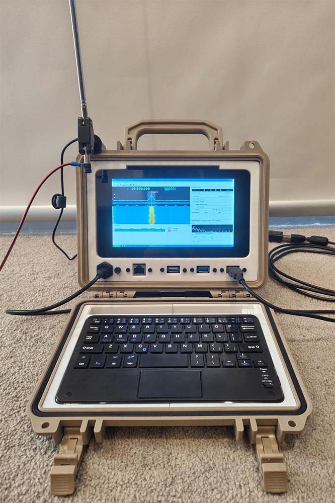
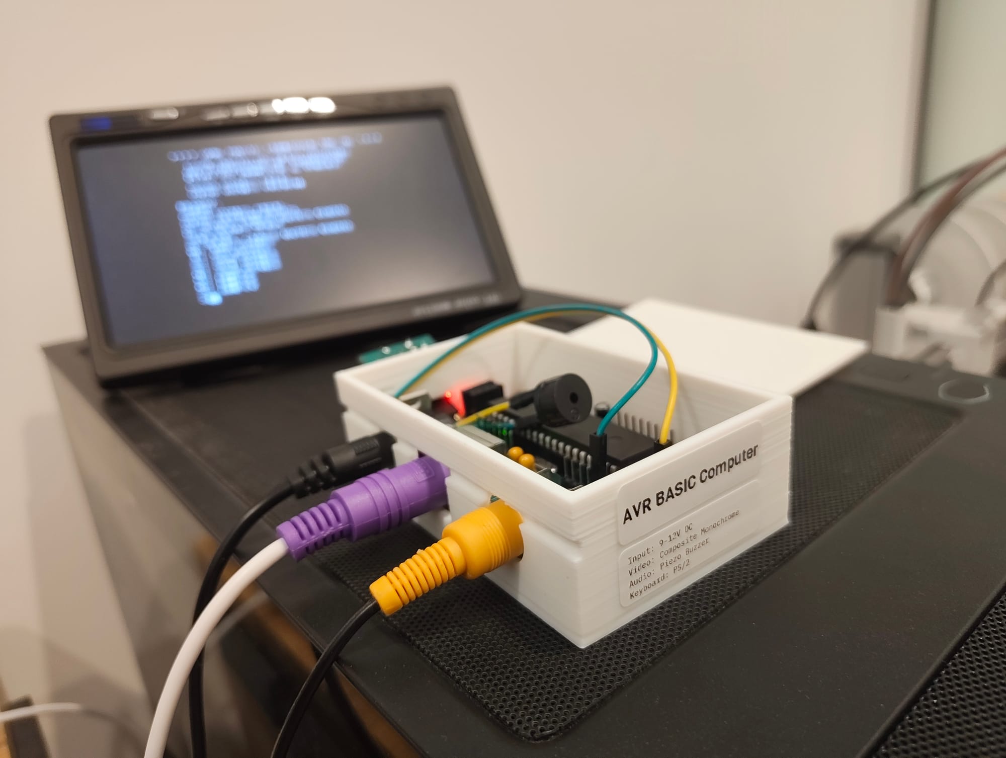
Booting up the AVR BASIC Computer.
This build is based on Dan's Single Chip AVR BASIC Computer. It uses an ATmega1284p microprocessor which is in abundant supply in the present day and will run you about AUD$12 a piece. This MCU can be thought of as an Arduino's big brother, with specs like:
- Supporting a max clock of 20MHz
- 128KB of In-System Programmable Flash, 16KB of SRAM, and 4KB of EEPROM
- 32 programmable I/O lines, 8-channel 10-bit ADC, 2 USARTs, 1 SPI interface, and 1 TWI (I2C) interface.
- Two 8-bit and two 16-bit Timer/Counters, along with 6 to 8 PWM channels depending on the specific variant and configuration.
All this to say, it can handle a lot for what it is!
With the help of Claude Code I was able to extend the TinyBASIC Plus library to add rich features and make a complete retro home computer that you would expect to see during the 1970-80s.

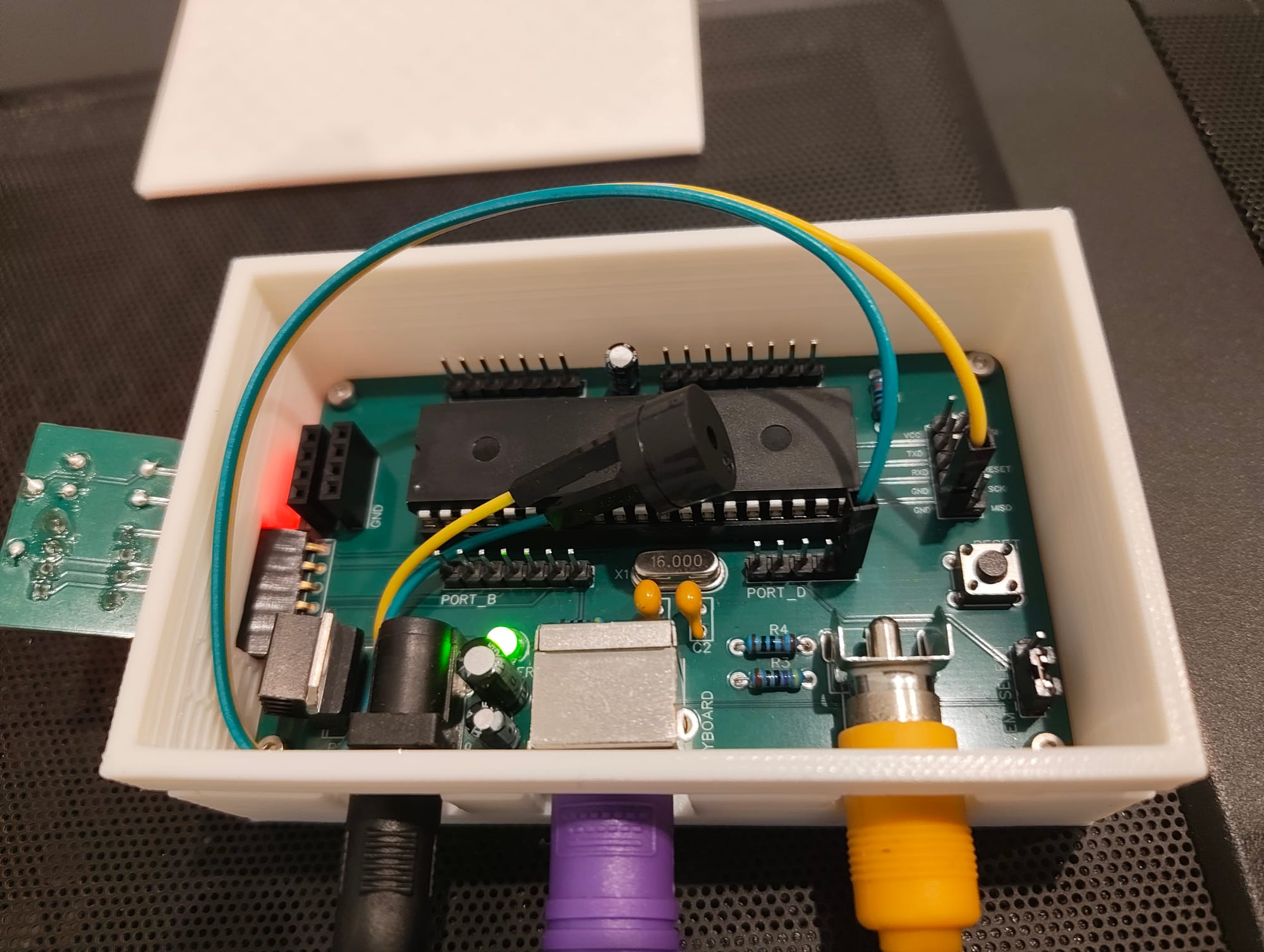
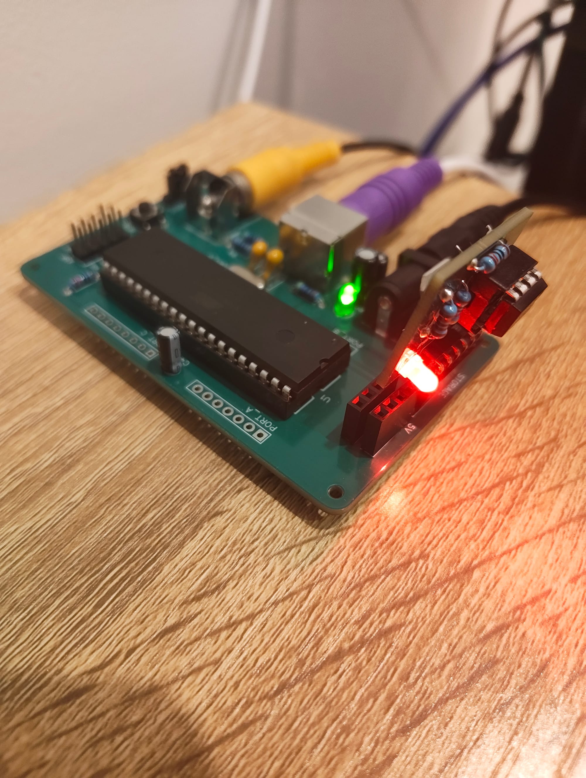
The circuit consists of only a few common passive components and some sockets for power input, video out, and keyboard support. Notable components are a 7805 voltage regulator to supply constant 5V to the computer, the ATmega1284 chip itself, a 16MHz clock, a handful of capacitors for decoupling and a reset switch + power LED.

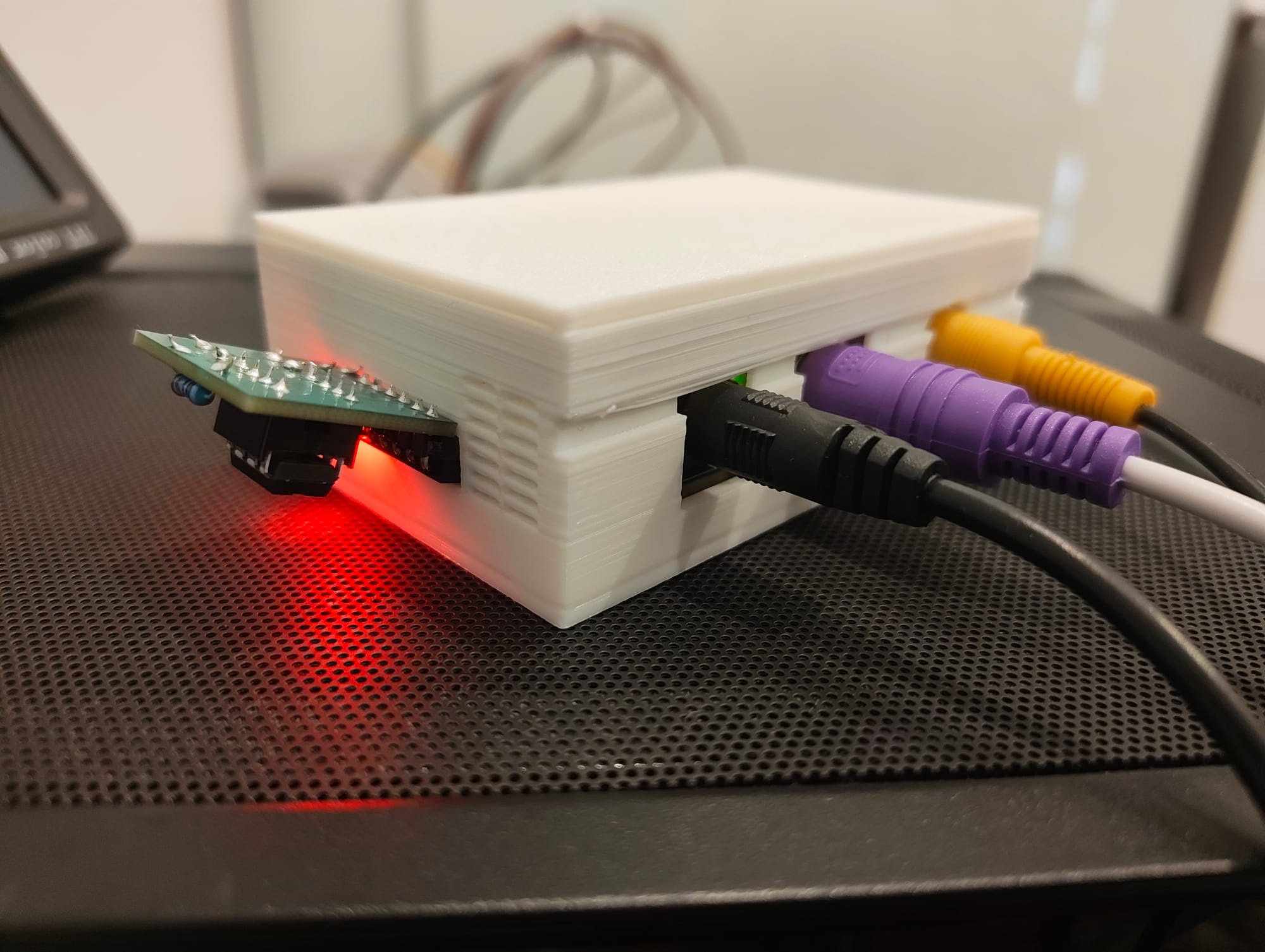
I had a lot of PCBs manufactured by JLCPCB for a few dollars delivered, this made the entire process not only easy but extremely rewarding - the boards look great and adds a professional touch to this project.
Showcase of features
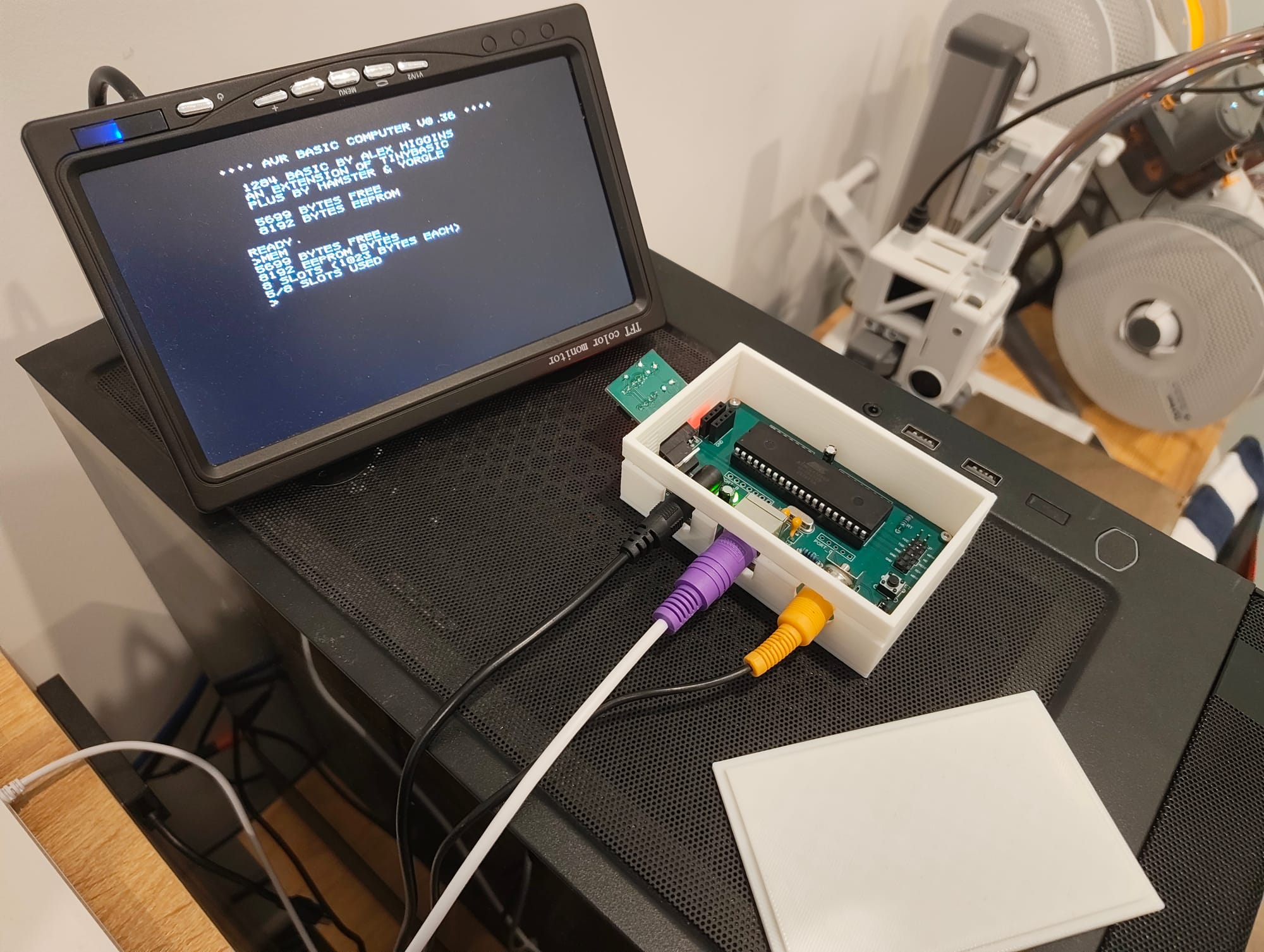
The prompt featuring a blinking block cursor.
I wanted the prompt to look and feel like it belonged in the past, it mirrors countless designs seen in the original line up of computers of the time. It amazes me to see we are working with bytes of memory - not what we are used to today with our gigabytes and terabytes being mainstream units of measurement.
In a similar sense, it amazes me just how far we can get on so few units - this machine demonstrates a level of elegance in its simplicity. The constraints imposed on the user brings about a certain creativity that is otherwise not required to use present day computers - this makes it really fun and enjoyable to use.
Listing a pre-written program.
Programs are stored in memory by writing numbered lines, it is a very natural way to address the limited resources of this system while still being user friendly. Made a mistake with line 20 of your code? No problem, at any point just type 20 followed by the new code and hit enter, this line is now updated and ready to be re-run.
Drawing a circle.
One of the most iconic things I have always heard about people who grew up with BASIC is the ability to draw shapes. Circles, lines, and pixels can all be drawn by the user within the prompt by specifying key attributes.
Plotting a parabola.
It doesn't all have to be fun and games however, users can plot real mathematical curves within the interpreter. You can even specify the [x, y] bounds you wish to focus on.
What you need
You will need the following components if you want to build one of these yourself:
- L7805 regulator for 5V
- ATmega1284p MCU
- A 16MHz crystal oscillator
- Resistors (in ohms) of values: 470 x2, 1k, and 10k
- Electrolytic capacitors of values: 0.33uF, 0.1uF, and 4.7uF
- Ceramic capacitors of values: 22pF x2
- 40 pin DIP header to seat the MCU
- RCA port
- 2.1mm DC barrel jack
- PS/2 port
- Pin headers (male or female)
- A pin header jumper
- A 3mm LED
- A switch
- A printed circuit board if not using breadboards or the like
Basically, all of these electrical components are easy to find especially on sites like AliExpress - though I'd recommend ordering the ATmega1284p from somewhere reputable like Mouser.
How to make it
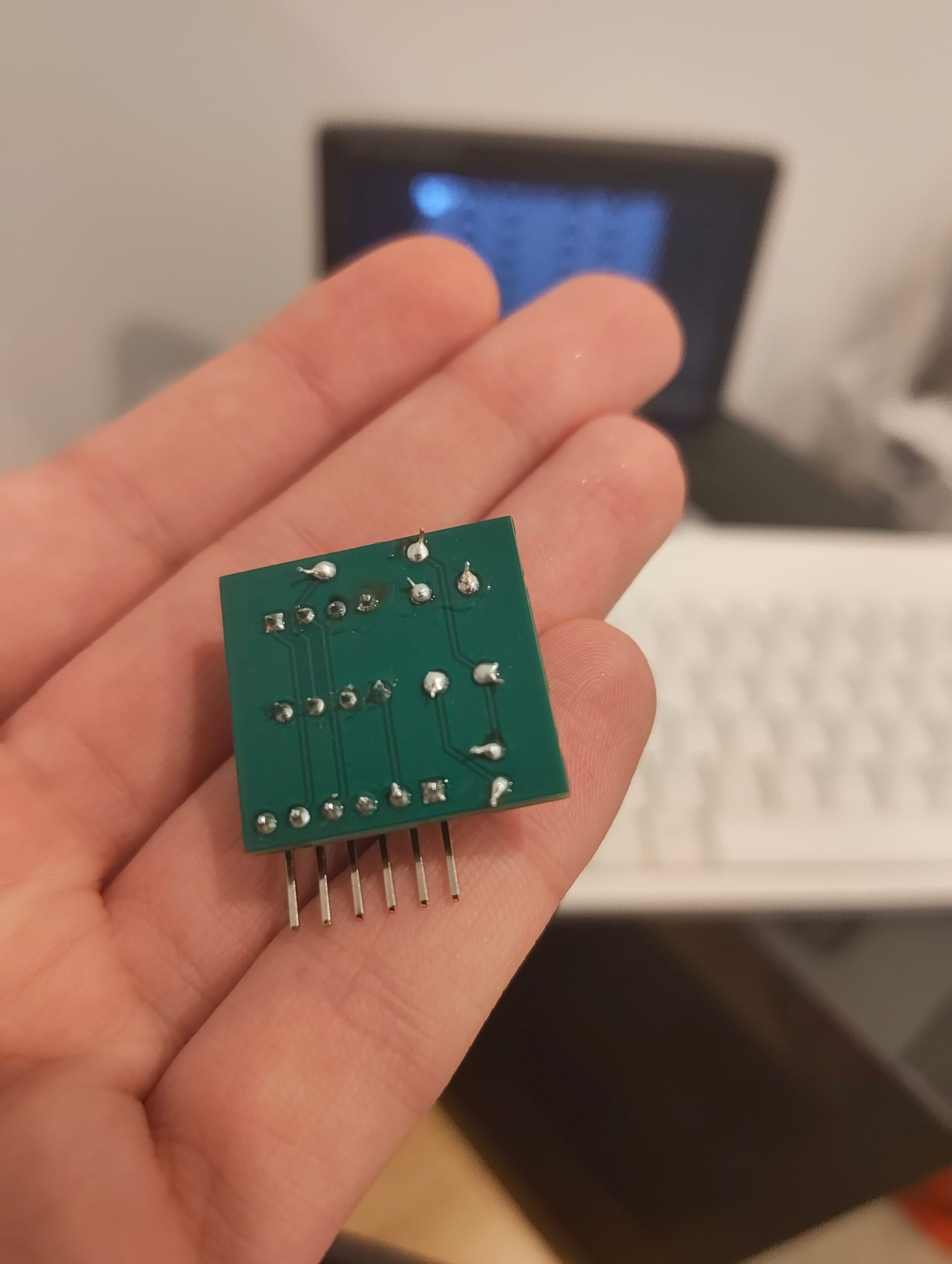
The process of assembly is quite straight forward especially if you bite the bullet and try to understand the schematic. If you print the circuit board then it is probably even easier to follow because you simply place each component, as numbered in the schematic, on to the board.
At that point you're just soldering everything on the underside of the board and there really isn't much to it.
How to program it
This is where things can get tedious, but I have found much success using the Arduino IDE to flash the board via a USBasp programmer (these are pretty cheap and readily available).
You will need the following libraries added to the Arduino IDE:
- TVout (and TVoutfonts)
- ps2uartKeyboard
- SpiEEPROM
- SD
You will also need to add the following package to the Arduino IDE board manager:
- MightyCore
All of this is available in my repository:
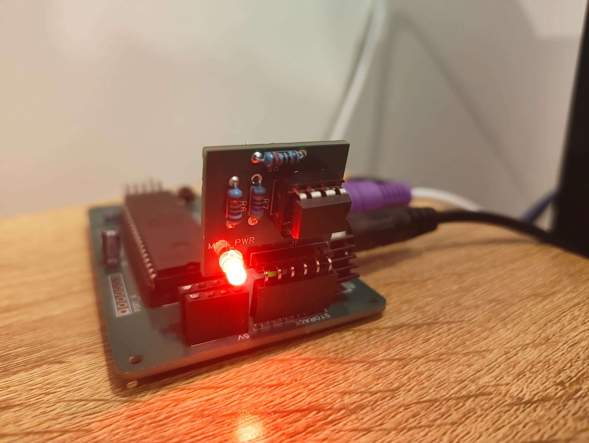
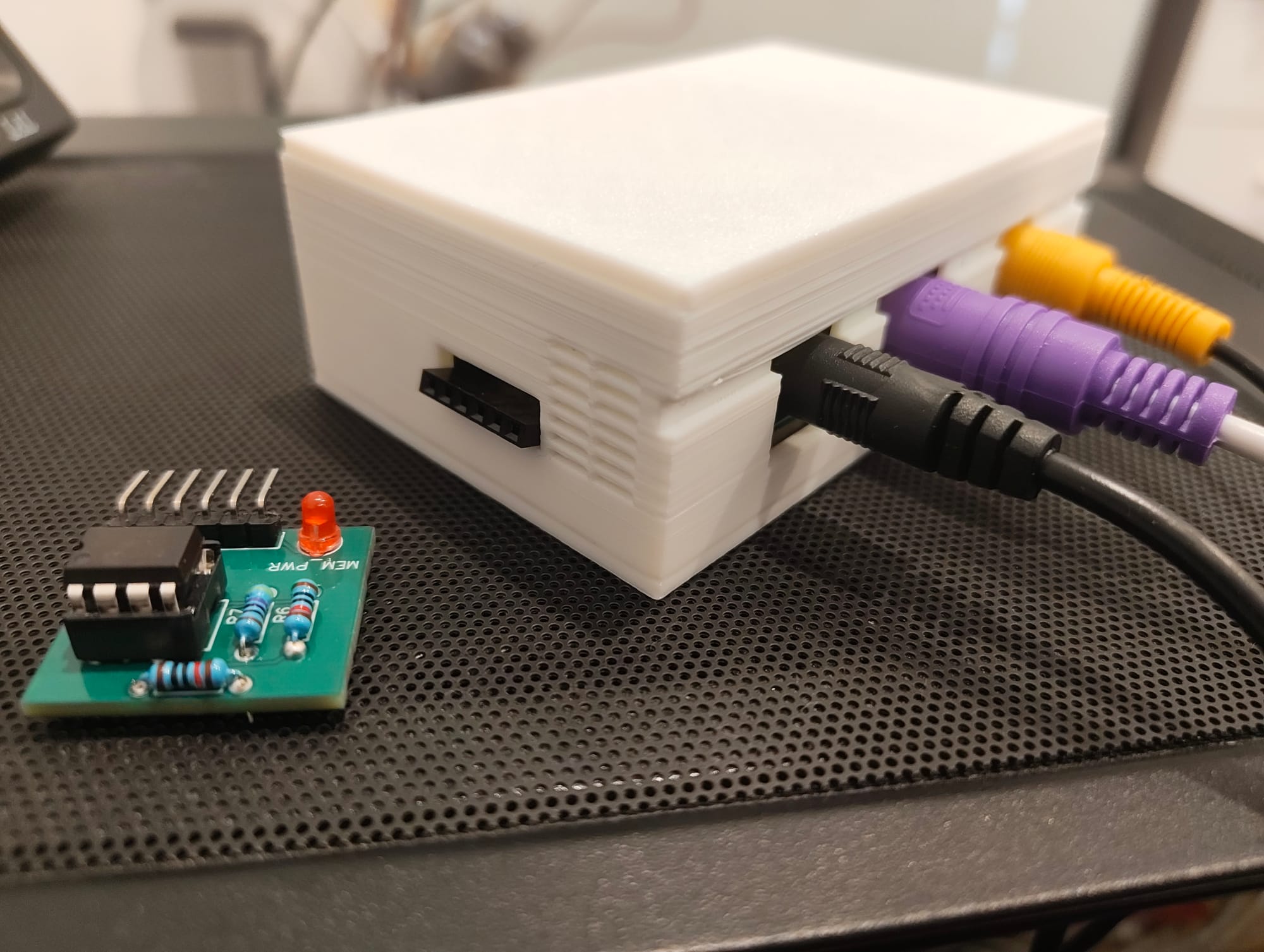
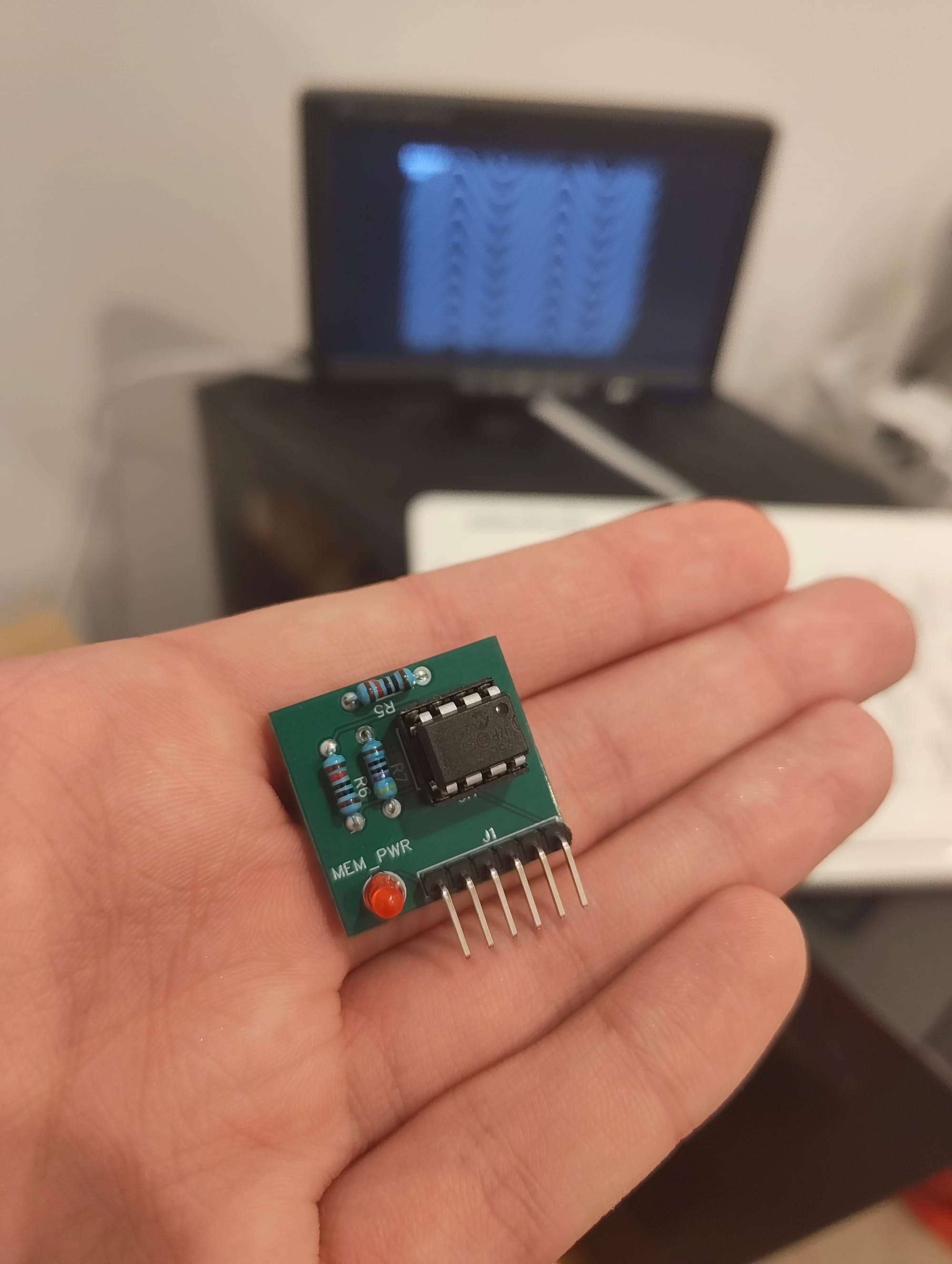
Memory cards, 3D printed cases, attachments, and piezo buzzers - there's plenty of fun to be had!